For a while I thought to write about an OpenStack cheat sheet showing OpenStack components, so you can refer to it as an easy to use handy reference.
If you are using NFV, you are using OpenStack for sure. OpenStack sits at the VIM layer inside NFV MANO and is the most important piece to manage the cloud infrastructure. For a quick refresher on NFV, click here, NFV Cheat Sheet.
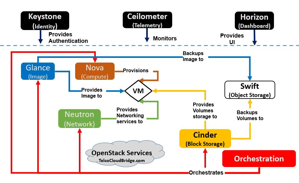
Openstack is very complex. You hear a lot of terms like Cinder, Glance, Nova, Horizon, etc. They are quite confusing to know and remember. So here I made a small OpenStack cheat sheet as a diagram/infographic which you can keep as a reference. Just match the block colors with the colors of lines and you will easily know the role of each component/block and how they interact with the other blocks.
How about sticking a copy of the diagram on your desktop for easy reference !
What is OpenStack?
“OpenStack is a cloud operating system that controls large pools of compute, storage, and networking resources throughout a datacenter, all managed and provisioned through APIs with common authentication mechanisms”. “https://www.openstack.org/software/“
So here is the cheat sheet/infographic about Openstack services.
Do take a note however that there are many more services in openStack, here are the most important core ones that you must know
OpenStack Cheat sheet for Core Services-Simplified from openstack.org
Description of OpenStack Cheat sheet
Horizon ( Dashboard)
This allows users to work on OpenStack using web GUI instead of CLI. This provides a user-friendly dashboard. This is part of common services
Ceilometer ( Telemetry)
The ceilometer is a component of the Telemetry project. Its data can be used to provide customer billing, resource tracking, and alarming capabilities across all OpenStack core components.
Keystone ( Identity)
keystone is the simplest service in OpenStack. it is a core service and provides authentication and authorization of tenants in OpenStack.
Nova ( Compute)
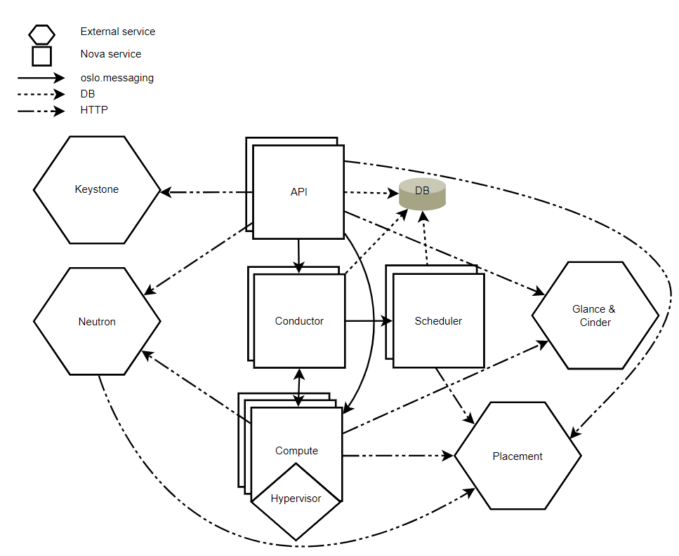
Nova is the original core component of openstack and considered one of the most complicated components in openstack. It providess compute service in openstack.
The nova-compute is responsible for creating and termination of VM instances via hypervisor APIs ( for example Libvirt KVM, VMWare API for VMware)
Nova Conductor
The Nova conductor provides database access to compute nodes. The logic is to have all the database access pass through Nova conductor instead of compute nodes accessing DB directly thus reducing the risks in case of compute node gets compromised.
Nova-api
The nova-api component accepts and responds to the end user and computes API calls.
Nova-Scheduler
Compute uses the nova-scheduler service to determine how to dispatch compute requests. For example, the nova-scheduler service determines on which host a VM should launch.
Neutron ( Networking)
Neutron is a service that provides networking service to other components of OpenStack
Storage
There are various type of storages in openstack. It is important to understand the difference between them
Cinder (Block Storage)
Cinder provides block storage in OpenStack. It provides raw volumes that can be used as a hard disk in virtual machines. It is called block storage because a large amount of data is chopped into blocks and stored with a unique identifier is attached which allows the data to be retrieved quickly and efficiently.
Use Cases:
Databases-Block storage is common in databased and other mission-critical applications that demand high performance
Volume snapshot management
Attaching or detaching volumes from instances etc
Creating and deleting of a snapshot of the volume.
Swift (Object Storage)
Swift provides an object-based storage service and accessible through Rest APIs. It can easily scale, making it a great choice for public cloud storage.
It has static nature and writing objects is a slow process, so does not work well with traditional databases. ( for which cinder works well). S3 from Amazon is a good example of object base storage.
Glance (Image Registry)
Glance also provides storage but acts only as an image registry. It keeps track of virtual machines images, metadata such as the kernel, disk images, disk format, etc. This is available to OpenStack users through REST APIs.
Heat- Orchestration
Heat manages and automate/orchestrates entire life cycle of infrastructure that includes servers, IPs, volumes, security groups, users etc.
So thats it about the core services in OpenStack; let me know in the comments if you have any comments on this piece and if this cheat sheet helped you or not.
What is Kubernetes ? and how is kubernetes architecture ?
To start with, Kubernetes, also known as “K8s” is an open source container orchestration platform that automates the deployment, management, load balancing, and scaling of container based applications ( also called containerized applications).
Secondly, Kubernetes is a leader in container orchestration as this survey shows. In fact, It can orchestrate thousands of containers using open source code. And since it is open source, a K8s cluster can run almost anywhere including public cloud providers ( e.g. all major cloud providers like Amazon Web services, Azure)
Indeed Kubernetes is an enabler for Platform as a service (PaaS) that creates hardware layer abstraction for development teams.
Why do you need to know about the Kubernetes?
Today, majority of applications are developed as cloud native, i.e. they run as microservices/containers. Due to their lightweight size, they have become popular. 5G core, for example, is completely cloud native based. As Kubernetes is popular container orchestration platform, so it is important to know about this platform.
The best way to understand and appreciate Kubernetes is to understand its architecture.
The Best way to understand “what is Kubernetes” is to understand its architecture.
So as you are looking to know about “what is Kubernetes”, i suggest that understanding its architecture can clarify it.
However, the info out there makes Kubernetes architecture hard to understand.
In this step by step guide, I will make it very easy for you to understand the Kubernetes architecture clearly.
I will make Kubernetes easy to understand through the ship analogy
I will draw parallels between Kubernetes and cargo ships. This is an interesting analogy and you would not forget the concepts after that.
Before understanding the Kubernetes and using the ship analogy, it is good to understand first some basic terms like Pod, cluster, and Node.
In fact, Kubernetes is architected as a cluster of nodes, and then containers are deployed into pods using Control Plane. The control plane manages the nodes and the pods.
Concept of Pod, Cluster, Container, and Node
Let’s first understand the hierarchy going from small to bigger.
Container > Pod > Node > Cluster
This order will help you remember, smaller to the bigger size. The smaller resides in the bigger.
Concept of Pod, Node, container
Container
This is the level 0.
Kubernetes.io defines container as following“A container image is a ready-to-run software package, containing everything needed to run an application: the code and any runtime it requires, application and system libraries, and default values for any essential settings”the container is the smallest unit and sits inside the Pod. However, Kubernetes does not create containers. That is the job of the container runtime, such as Docker ( more at the end)
Pod
This is the level 1.
The container sits in the Pod. A Pod is defined as a logical unit of application. It can contain one or more containers and is deployed on a node. For Kubernetes PoD is the basic unit ( instead of containers) i.e Kubernetes deploy Pods ( which have containers inside) and does not create containers directly. Normally Pod will have a single type of application or it can have multiple applications if they are closely related. Each pod is assigned a unique IP address within the cluster, that enables the application to use ports without conflict. Pod to pod communication is enabled using a dedicated Pod IP address
Node ( Worker Node)
This is level 3.
Pods run inside nodes.
Nodes can be virtual machines or physical servers. A Node is a worker machine in Kubernetes. Each Node is managed by the Master. ( more about worker node and master node later on) A Node can have multiple pods, and the Kubernetes master automatically handles scheduling the pods across the Nodes in the cluster.
Node is also called worker node in Kubernetes.
Cluster
This is level 4.
At the minimum, the Cluster contains one or a group of nodes and a control plane. containers do not need to be tied to the specific virtual machine. Containers can run anywhere, on physical, virtual, or cloud but what ties them together is them being part of a cluster.
Kubernetes clusters are comprised of one master ( more on master later on) and a number of nodes ( also called worker nodes)
After getting the clarity on the master and worker node, let’s see the reference architecture of Kubernetes and the role of master and worker node.
But the best way to understand what is inside the master and worker node is to use the ship analogy.
Lets take the next section of understanding what is kubernetes and kubernetes architecture.
Kubernetes architecture using ship analogy?
Kubernetes analogy to Ships
Worker nodes are like cargo ships. Cargo ships take containers from source to destination. In Kubernetes, worker nodes host containers of applications. Master is like control ships. Control ships manage and monitor cargo ships
Let’s take a look at different components of the control ship/master
What is inside the master (Control ship)?
Master components in Kuberentes
The master runs control plane components. The control plane components make global decisions about the cluster as well as detecting and responding to the cluster events. Usually, control plane components are run on a dedicated machine in a cluster.
Kube scheduler
Kube scheduler= Cranes in control ship
When cargo ships arrive, containers are loaded on them using cranes, , therefore there should be a way to identify where to place the containers, which ships have the capacity, constraints, etc. This is the job of the schedulers. But as Kubernetes run pods ( containers are part of the pods), so we can say that kube scheduler schedules pods on the ships ( on the worker nodes)
The scheduler takes into account the resource needs of the pods, such as CPU or memory, along with the health of the cluster. Based on this, it can schedule pod to the appropriate compute node
etcd
etcd= cargo ship profiles
As containers are loaded and unloaded from ships on daily basis. There should be a database that needs to keep track of all this information on where are those containers and at what time they are uploaded. etcd is a database that stores this information ( It is like a source of truth) This is analogous to a “cargo ship profiles” that has details of all such information.
kube api server
api server = The department in control ship that manages communication
There are multiple offices onboard a ship. As well there are external stakeholders. Who manages the communications within internal and between the internal and external entities? kube-api server serve exactly that purpose
kube controller manager
Kube-controller-manager = captain of the master node
Kube controller manager
In Kubernetes, the kube controller manager runs a different kind of controllers that control different functions like ( it is like the captain of the master node)
Node controller- responds when nodes go down
Replication controller-responsible for maintaining the correct number of pods
End point controller-Populates the endpoint objects like joins, services, and pods.
In ship analogy, kube controller manager is managing different offices in dock like operation office ( the team that responds if any issue with the worker node), replication office (the team responsible for maintaining correct number of pods)
What’s inside the worker node (Cargo ship)?
Kubernetes architecture
kubelet
Kubelet =captain of the worker ship
This is an agent that runs on each node of the cluster. It listens to instructions from kube-api-server and manages the Pods and the containers running on the machine.
kube proxy
kube proxy= manages communication between worker ships
kube proxy manages communication between different containers deployed across different nodes. For example, a packet core may have multiple different services, one service deployed on one node, while another on another node that needs to talk to one another, the kube-proxy facilitates this kind of communication
In terms of ship analogy, kube proxy manages communication between different worker nodes.
container runtime
You need to install a container runtime into each node in the cluster so that Pods can run there.
Container runtime is installed in each node in the cluster so that pods can run there. Docker is one of the popular container runtime but there are others such as the Open container initiative.
So thats it, I hope it is clear now on what is Kubernetes and Kubernetes architecture. Please leave a comment below and let me know your thoughts on whether it is now easy for you to understand Kubernetes ?
Answering this question is important as everyone talks about Cloud Native but very few are aware of all the attributes of Cloud Native applications and architecture.
For example, many associate cloud native to the use of the containers only. which is not correct. As there are other attributes that also an important part of cloud native software architecture, so just the use of containers does not qualify an application to be cloud native.
Then there is a common misconception that containers and microservices are one and the same thing. which is not true.
Hence, this article aims to clarify all these concepts related to cloud native in a simple and easy manner.
It is important to know these attributes as all the future IT and Telco applications that are supposed to run in cloud are being evolved to cloud native software architecture.
When it comes to the Telco industry, it is a big paradigm shift. NFV was originally developed with VNF in mind which is one large piece of monolithic software on a virtual machine, whereby the latest trend is the transition to cloud native CNFs which are lightweight, agile, and containerized. Therefore it is important to know about cloud native in general.
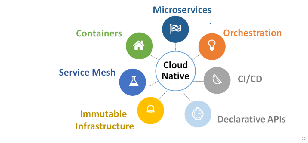
Here I have made the text bold which are the necessary components of cloud native ( as per CNCF) and moving forward we define them one by one.
Cloud Native Definition according to CNCF
“Cloud native technologies empower organizations to build and run scalable applications in modern, dynamic environments such as public, private, and hybrid clouds. Containers, service meshes, microservices, immutable infrastructure, and declarative APIs exemplify this approach. These techniques enable loosely coupled systems that are resilient, manageable, and observable. Combined with robust automation, they allow engineers to make high-impact changes frequently and predictably with minimal toil“
I made the important attributes are made bold here and converted them to seven major attributes for easy reference so that you know , what is cloud Native
Fig: Cloud Native attributes
What is Cloud Native? The Seven Attributes
1. Containers
Virtual Machines are good. But containers are better.
How?
VMs let you isolate applications from each other on the same server without the need to buy a server for each application. However this comes with one caveat- each VM uses a lot of system resources.
This is because it makes a virtual copy of everything including the operating system. Think of it as running one Linux instance ( Operating system for VM) on another Linux instance ( host operating system).
And when one starts adding VMs in cloud, the solution becomes expensive.
On the other hand, multiple containers can share the same host operating system ( Linux kernel). This makes containers lightweight, portable and fast to start up. This makes them very stuitable to be deployed in cloud and hence the name cloud native.
One famous and most popular container example is Docker.
2. Microservices
A microservice is a way to build applications as small pieces of software.
Today’s applications are big monolithic pieces of software For example think of it as an EPC (Evolve packet core) made as one big monolithic application. It is difficult to upgrade the software of such an application considering the software pieces are tied together as one big piece and with so many moving parts, it is a complex task to evolve and upgrade the software of such application by the developers.
On the other hand microservices work as small applications ( each called a microservice) that are loosely coupled. This creates a pluggable application architecture. each microservice communicate with each other through REST APIs.
Advantages:
Each microservice can evolve independently, has autonomous life cycle. There is no need to wait for quarterly releases to be deployed. upgrades can be rolled out quickly. Each microservice can scale on its own without waiting for the other services to scale. This is the true essence of being a cloud based application.
Are microservices and containers one and the same thing ?
Not exactly.
You don’t need a container to run a microservice. Instead, you may run each microservice in a separate virtual machine. But would that be an efficient solution ?
No !
Each VM has assoicated overhead of an indpendent operating system. This makes it inefficient and very heavy to run many microservices in multiple VMs.
On the other hand a container is much suitable to run a microservice i.e one microservice per container.
That is the reason that when we say a microservice, we usually mean the containers and vice versa.
3. Orchestration
Docker create images and run containers.
However when talk about hundred and thousands of containers, we need a good management tool.
This is done with a special program called container orchestrator or simply an orchestration tool.
CI/CD ( also sometimes refered as Devops) is an essential part cloud native architecture.
The whole concept of microservices is having software agility and CI/CD can achieve that objective efficiently.
CI/CD is set of tools and practices that support accelerating software development cycles. CI/CD tools automate stages of the software release cycle. Small incremental changes are made to applications.
Then there is a process of continuously integrating and testing these changes in small increments.
As each microservice can be evolved and upgraded separately than other microservices, there is a less risk of rolling out upgrades to the network continuously. This is called continuous integration and continuous delivery of new code and hence brings software agility.
5. Declarative APIs
Microservices communicate through APIs. There are two kind of APIs
Imperative APIs
Declarative APIs
Imperative APIs tell the system on the exact steps of how to perform an operation. Declerative APIs just leave an intent or wish on what it is expecting from the system and leaves it to the system on how to perform it.
A good example would be if I tell someone to cut the grass in the garden and then tell him the exact steps, tools etc on how to cut the grass ( imperative API)
VS
I just tell him to cut the grass and leave it to him to follow his way ( Declarative API)
The modern applications work with declarative APIs and that is the recommended approach in cloud native architecture. The advantage with the declarative APIs is that one microservice does not need to understand the details of the operation it wants from a second microservice. This makes the integration quick , easier and developer friendly.
6.Immutable Infrastructure
Mutable is defined as anything that’s capable of being changed. Traditionally servers are mutable, as they are continually updated, their configurations are tweaked.
However here is a question, in a cloud like environment, do you really need mutable infrastructure, as this means there will be a challenge to keep the configurations updated and more importantly consistent across clusters.
On the contrary, a better way is to just kill the server and bring up a new server when there is a need to upgrade the server. Which by the way, can be done faster these days. This gave birth to the concept of immutable infrastructure. This refers to servers or VMs which are never modified after deployment. Instead of updating the server, we just replace it with a new version. For any updates or modifications, you will build up a new server from a common image and then decommission the old server.
The biggest benefit of immutable infrastructure is consistent and configuration across all environments ( dev, test, production). Deployments are simpler and predictable and testing the infrastructure is much easier. This greatly simplifies the operation and maintenance of infrastructure in the cloud environment.
7.Service Mesh
This is the last attribute of a cloud native environment.
With hundreds of microservices deployed, there is an increase in service to service communication. Service meshes manage this complex web of service communication in a fast and reliable way.
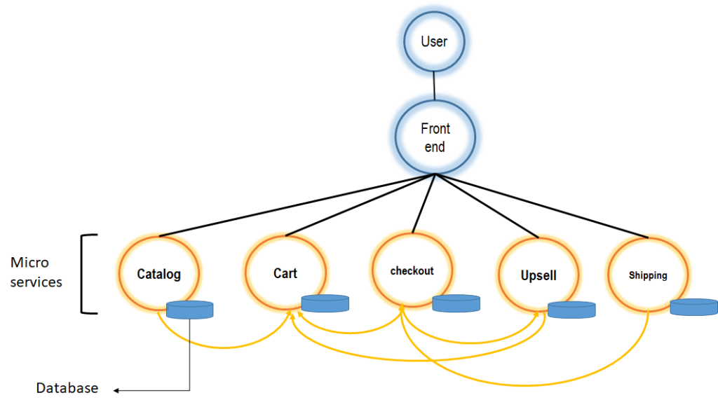
To understand the concept of service mesh, consider the following example
a
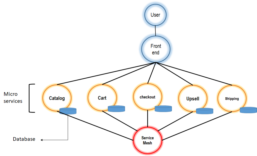
A user comes to buy something on an eCommerce website. He visits the catalog of products, adds a product to cart, proceeds to checkout. At that stage, he is given the option to upsell, which may take him back to the cart. There is a lot of communication between different services here.
This was a simple example. In practice, there are a huge number of microservices. A better approach is to have a service mesh, which can manage service to service communication avoiding as service to talk to any other service directly.
Conclusion-What is Cloud Native?
So that’s it, these were the seven attributes of cloud-native according to CNCF and hopefully, it should clarify “what is cloud Native”.
Now let me know in the comments section, if you have any questions or think I missed something important that should be an attribute for cloud Native.
However, here is a question, why you need a separate MEC architecture ? Why not re-use NFV architecture.
When NFV can run itself any application, isn’t MEC one of the applications? I got quite a few questions on this, so I thought why not write a dedicated article on this one. This article will clearly position MEC vs NFV and conclude with some takeaways for you.
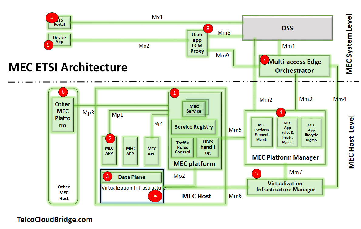
If you are new to NFV and MEC architecture and haven’t read about my last article you can read them here. NFV architecture here and MEC architecture here.We discussed the MEC architecture in our last blog ( link above) . I have now labelled each component with a number code so you can recognize them once we move them to NFV.
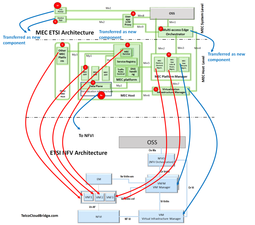
lets add to this to NFV Architecture which is below ( The famous ETSI Architecture)
MEC in NFV
Lets start moving the items from MEC to NFV.
You probably have guessed it correct, a lot of MEC architecture components are just VNFs which can be easily moved to NFV as VNFs.
MEC Components that become VNFs
I have now elaborated it through a diagram in which I have shown which components from MEC can be mapped to NFV architecture as VNFs. I have shown all of them with red arrows. ( items 1,2,3,4,6)
They are
All MEC Apps
MEC platform
“MEC Platform Element Management” and “MEC App Rules & Reqmts Management”
Other MEC Platforms
Data Plane of MEC Platform
After moving these components as VNFs, it would logical to ask is there anything I can re-use from NFV so that I can remove from MEC architecture.
Components that are not needed in MEC architecture as NFV already have them
Well, MEC has a virtualization stack ( the Virtualization Infrastructure manager(VIM) and Virtualization infrastructure); So does NFV- VIM and NFVI Correct ?
So why would you need a duplication here.
So we can easily remove them from MEC as NFV can handle them. As shown in the diagram below item 3a and item 5 are mapped respectively to NFVI and VIM respectively.
So far so good !
With this mapping we can see now new components added to NFV with the codes so you can track.
The VNFM does the life cycle management of VNFs ( creation, deletion, maintenance)Now that MEC functions are converted into VNFs, we would naturally need corresponding VNFMs. This is done by two VNFMs as following.
VNFM to manage life cycle of MEC Apps. ( item 4b)
VNFM to mange life cycle of MEC Platfrom ( new item)
Just to elarborate more. The item 4 above in MEC is decomposed in 4a and 4b as following.
MEC platform Element Management and MEC App rules & requirements management” becomes a VNF labeled 4a
“MEC App life cycle management” is mapped to VNFM as item 4b
Lets move ahead !
Multi Access Edge Orchetrator
With all other items mapped correctly, we are left with one major component which is MEC Orchestrator.
This component ( item 7) is mapped ” as-it-is” and re-named to Multi Access Edge Orchestrator. This is now a new component in NFV. Likewise items 8,9,10 are mapped “as-they-are” in NFV as new components.
Conclusion: Does NFV cover everything MEC offers ?
Perhaps Not.
While MEC architecture can be completely mapped to NFV. What NFV cannot provide is the MEC orchestration part. Neither can NFV provide the CFS portal, Device App, Use App LCM proxy.
Among them MEC orchestration is the most important component that is missing in NFV.
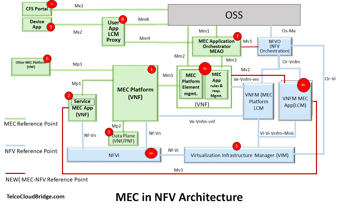
If you look at the original diagram of MEC at the top. This sums up to the top layer which is “MEC System level” which is the missing part in NFV ( of course OSS stays the same). Also mapping MEC in NFV architecture results in some new reference points ( refer to the legend in above diagram), the new reference points are colored as maroun.
So thats it from my side; hope this makes the situation more clear on how MEC fits inside NFV architecture.
Now its turn to drop me a line, if you have some questions here !
MEC or Multi-access Edge computing will draw the next wave of investments by Mobile operators who want to take advantage of low latency services that 5G promises. Which means running services closer to the consumers ( that is close to radio sites).
This opens a new range of services and new ways to monetize for service providers. For example, faster gaming experience, Augmented/Virtual Reality, connected cars, etc.
And it has potential, that’s why you see the web scalers like Azure, AWS, Google have jumped to the bandwagon and suddenly started putting their cash in building their own MEC platforms.
I attended TechField day event( February 12 to 14th, 2020) in Silicon Valley US as one of the analysts, where we attended some very informative presentations from the participating networking vendors
Among those presentations, the one about CloudGenix’s SD-WAN, particularly, caught my attention, so I thought to write about it. (Please see full disclaimer at the end of the article)
This guest blog on MEF-70 is written by Anuradha Udunuwara – My friend and a Subject Matter Expert for Carrier Ethernet, SDN, NFV, and SD-WAN.
……………………………………………………..
You have probably heard a lot about Software-Defined WAN or SD-WAN.
So, you may know that It falls within the larger scope of SDx and Software-Defined anything ( if you are new, you can check this video to learn more about SDx and SDN)
Depending on the context, SD-WAN could mean a service, technology or an architecture (Just recall “Ethernet” – service (Carrier Ethernet), protocol (Data Link layer), interface etc.).
The terms SD-WAN ( Software-Defined WAN), uCPE ( Universal Customer Premises Equipment) and vCPE ( Virtual CPE) are used a lot these days, yet there is very little information on what are the differences and similarities between them i.e what is SD-WAN vs uCPE vs vCPE
So it is not uncommon that a vendor may mean virtual CPE but a customer understands it as a universal CPE and vice versa. And a vendor may present uCPE and the customer understands it as vCPE.
So this blog is an attempt to clarify and position these technologies in a simple way, so you can pick and choose the right one.
But this is not the only purpose. I will explain it in a way that you will understand the “WHY” behind each of these technologies. i.e. the motivation on why the industry adopted them in the first place.
We do it step by step starting with a traditional CPE and finally moving to the SD-WAN and uCPE. I recommend to follow the sequence in this way in order to have a clear understanding of SD-WAN vs uCPE vs vCPE
Traditional CPE
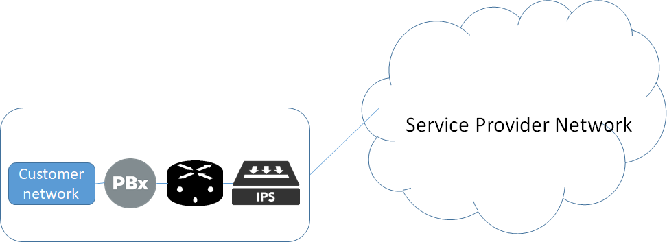
Traditional CPE, as you already know, is a physical box at the customer site. This CPE is usually a dedicated box like a router, a PBX, an IPS, etc. In the example below, there are three CPEs that are interconnected together so that packets are processed one after the other going through each box one by one.
Now as you probably have guessed that this is not a very efficient way for a customer to run his CPEs as he needs to manage multiple physical boxes that needs power and space. It is costly, CAPEX and OPEX wise and not a recommended solution today.
vCPE ( Virtual CPE)
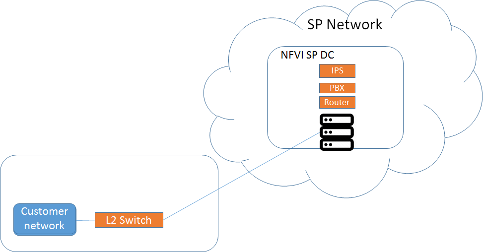
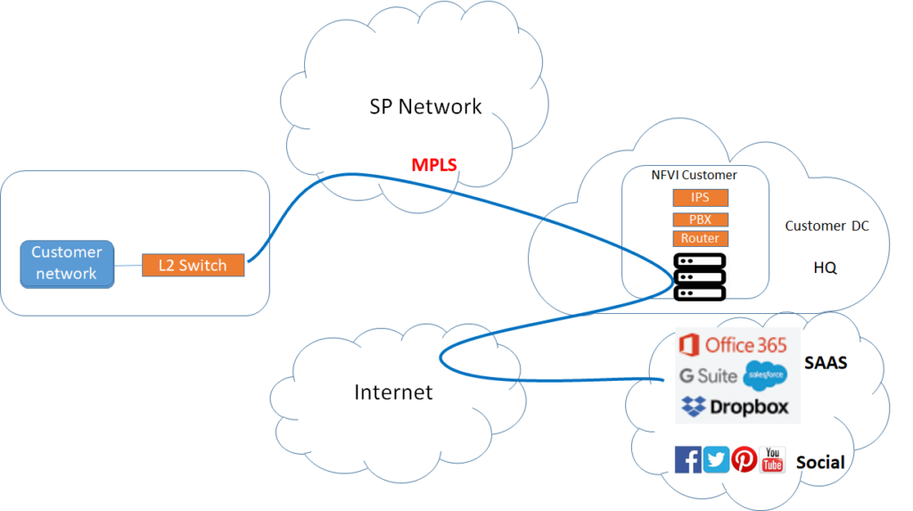
Virtual CPE is an answer to the issues presented by physical CPE. vCPE does not need to sit at customer premises. Thanks to NFV, CPE can run in the cloud today ( Reference: ETSI). Any CPE function like routing, firewall, IPS for a customer can be hosted at a data center on NFVI ( NFV Infrastructure). The customer can access the functions remotely through a simple layer 2 switch. Therefore, these functions do not need to run at customer premises. See the diagram below.
Now, this is both a win-win situation for a customer and Service provider. From a customer perspective, he does not need to host anything at his branch office ( power and space savings). From a service provider perspective, he can get economies of scale by utilizing x86 servers as a pool to provide CPE services to its customers.
There are two models for running virtual CPE. In the first model, the virtual CPE is hosted at the service providers Data Center ( DC) as shown below.
Comparing it with the traditional CPE, the exact same functions are shifted now to the NFVI DC of a service provider, while a layer 2 switch just provides a simple transport for the customer traffic to reach the NFVI PoP for processing purpose. What on-premises CPE was doing before is done by the off-premises CPE in DC.
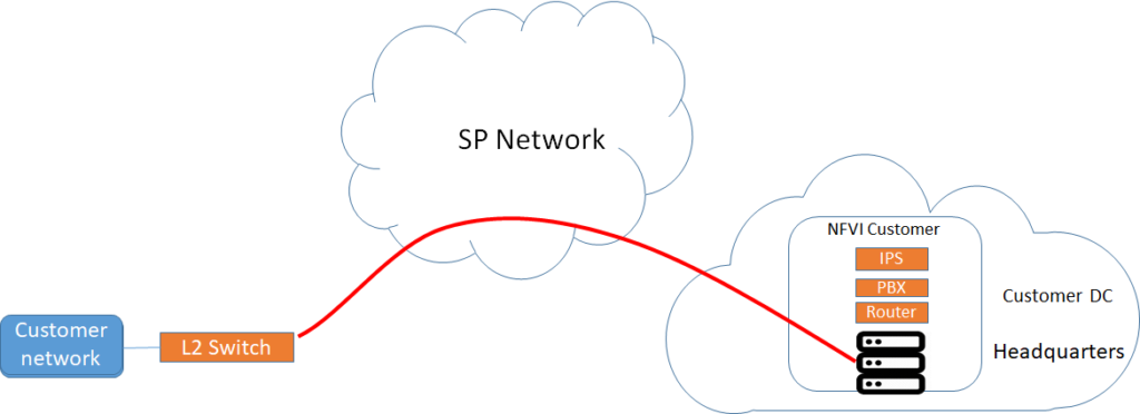
However virtual CPE is not limited to service provider’s DC. In a second model, virtual CPE can also be run at the customer’s own data center/NFVI as shown below ( insider customer’s HQ). In this model, the SP can offer the management of the NFVI but the NFVI itself runs on customer’s premises.
SD-WAN provides an overlay ( a separate network connecting CPEs whose characteristics do not depend on the underlay which is the actual transport like MPLS). This is a new type of connectivity that can use any transport network like MPLS and/or the internet etc. It provides seamless connectivity between customer sites using both MPLS and the internet. It does so by creating an overlay network over the underlay network ( MPLS or internet)
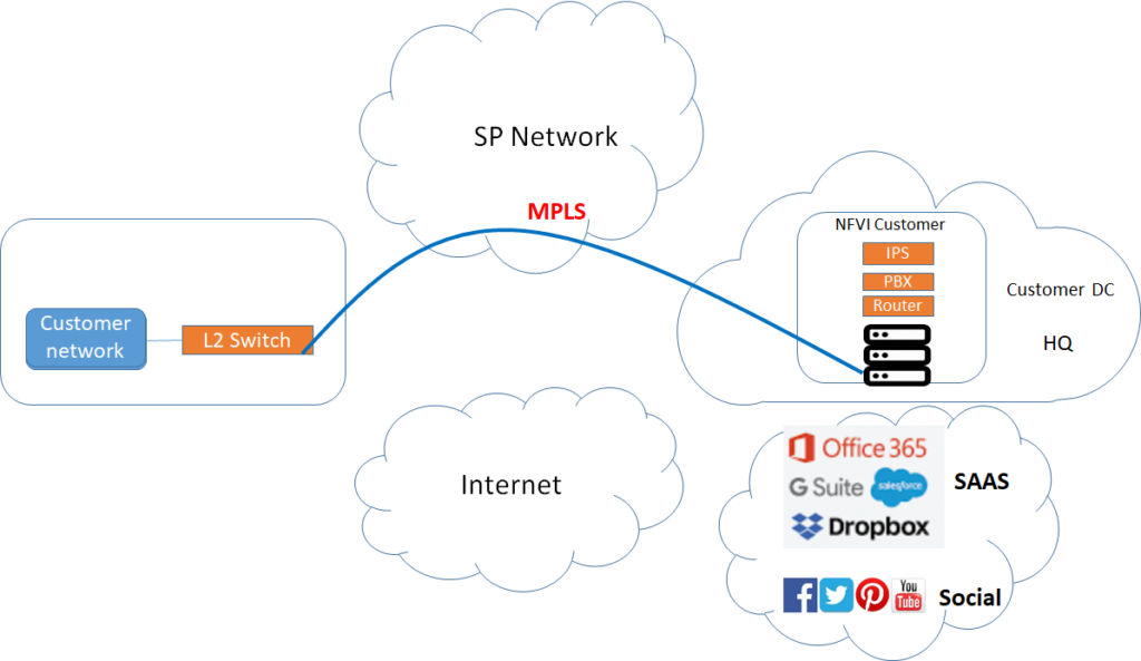
As you know that applications are moving to the cloud and more and more enterprises want to access their applications in the cloud ( also called SAAS). Therefore, let’s take the example of the previous customer topology and introduce a new “requirement” as shown in the diagram below. Before proceeding, consider that the current connectivity between the customer branch on the left and the customer HQ on the right uses an MPLS link from the service provider.
Here is the description of the requirement:
The customer has decided to use Microsoft 365 that is hosted on Microsoft servers at a remote location as a SAAS application.
The company wants to divert the social traffic ( like youtube, facebook) away from MPLS so as to offload some traffic from MPLS so backhaul cost can be reduced.
The customer wants to use the internet as backup transport for the MPLS link.
The traditional way to solve this problem would be as shown below. ( Although a partial solution)
To access the SAAS application, the branch will send the traffic through MPLS and which in turn will route the traffic through the internet to the SAAS cloud. There are two issues.
We have not been able to solve the requirement of using the internet as a backup to the MPLS link from the Service provider. ( which means, we may end up buying another MPLS from another SP, to be a backup for this MPLS link)
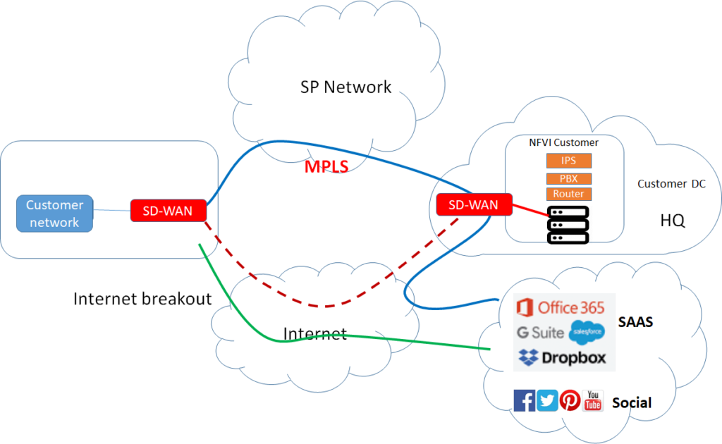
Welcome to the world of SD-WAN. SD-WAN solves exactly these issues. See below.
By adding SD-WAN physical CPE at the branch and HQ and creating SD-WAN overlay seamlessly on MPLS and the internet, we get the following benefits.
“Internet breakout” is achieved by providing a short path for the SAAS application to route through the internet ( The Green link) This is because the SD-WAN CPE is intelligent, so it can identify the application flows and knows which flows should be forwarded to HQ and which should be forwarded to the internet.
The social traffic is also offloaded from the MPLS link so it can use the internet breakout path thus reducing MPLS costs. ( Again the green link)
SD-WAN can seamlessly create a backup for the MPLS link over the internet path. ( Red dotted link)
We have killed multiple birds with a single stone, isn’t it? and this is the motivation for the SD-WAN today that it can provide an efficient way to route traffic directly over internet paths to applications that can reside outside the customer data centers.
uCPE -Universal CPE
OK, so where does uCPE come into the picture then?
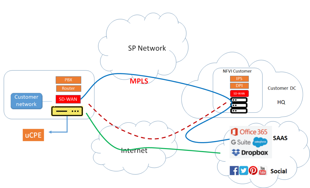
While the SD-WAN concept became popular, someone thought, why the heck one should have dedicated physical CPE for the SD-WAN. As SD-WAN can also be a virtual function. Why not just put it on a server or a white box.
And if I can put SD-WAN as one application on the server, why not put more functions. At this point in time, the concept of uCPE was born. The same server that runs SD-WAN can now host more functions, with the result that it is called now universal CPE and it sits essentially at the customer premises.
So we started with the physical CPE at the customer site and we returned to a uCPE which is also at the customer site. However bottom line is that applications can run anywhere, so it makes sense to have a flexible way to run it whether at a data center ( virtual CPE) or whether at the customer premises (uCPE)
So universal CPE is nothing but a server or a white box that can run multiple virtual functions. It can be SD-WAN or it can be other functions like routing, filtering.
Welcome to the new age. There is no place where applications should sit. Applications are not just in Datacenter of the service provider, they are in public cloud, SAAS cloud, private cloud. Therefore having CPE that can have both SD-WAN functionality and other functions does make sense.
So here are the key points
The focus of SD-WAN is on connectivity ( between customer sites and to the cloud) while the focus of virtual CPE is mainly on “virtual functions” like IPS, filtering, firewall, routing, etc..
SD-WAN can also be run as a virtual function.
When SD-WAN is run as a virtual function, it makes sense to be a part of uCPE in addition to other functions on the same box.
virtual CPE runs at the data center while uCPE runs at customer premises ( Both on servers)
Leave a comment below if you agree or otherwise to this explanation of SD-WAN vs uCPE vs vCPE